Controlling Hydraulic Oil Temperatures
With cooler weather on the way, you may not be too worried about rising oil temperatures, but the fact is, any industrial hydraulic system running higher than 140 degrees is too hot. Consider that for every 18- degree increase in temperature above 140 degrees, the life of the oil is cut in half. Systems that operate at high temperatures can produce sludge and varnish, which result in the sticking of valve spools. Pump and hydraulic motors bypass more oil at high temperatures, causing the machine to operate at a slower speed. In some cases, high oil temperatures can waste electrical energy by making the pump drive motor pull more current to operate the system. O-rings also harden at higher temperatures, leading to more leaks in the system. So what checks and tests should you perform if the oil temperature is higher than 140 degrees?
Causes of Heat Generation
Every hydraulic system generates a certain amount of heat. Approximately 25 percent of the input electrical horsepower will be used to overcome heat losses in the system. Whenever oil is ported back to the reservoir and no useful work is done, heat will be generated. The tolerances inside pumps and valves are normally in the ten-thousandths of an inch. These tolerances permit a small amount of oil to continuously bypass the internal components, causing the fluid temperature to rise. When oil is flowing through the lines, a series of resistances will be encountered. For example, flow controls, proportional valves and servo valves control the oil’s flow rate by restricting flow. When oil flows through the valves, a “pressure drop” occurs. This means that a higher pressure will exist at the valve’s inlet port than the outlet port. Anytime oil flows from a higher pressure to a lower pressure, heat is generated and absorbed in the oil. When a system is initially designed, the reservoir and heat exchangers are sized to remove the generated heat. The reservoir allows some of the heat to dissipate through the walls to the atmosphere. If properly sized, heat exchangers should remove the balance of the heat, enabling the system to operate at approximately 120 degrees F.
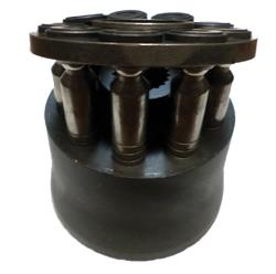
Figure 1. The tolerances between the pistons and barrel on a pressure-compensating, piston-type pump
are approximately 0.0004 inch.
Pressure-compensating Pumps
The most common type of pump is the pressure-compensating, piston-type pump. The tolerances between the pistons and barrel are approximately 0.0004 inch (Figure 1). A small amount of oil at the pump outlet port will bypass through these tolerances and flow into the pump case. The oil is then ported back to the reservoir through the case drain line. This case drain flow does no useful work and is therefore converted into heat. The normal flow rate out of the case drain line is 1 to 3 percent of the maximum pump volume. For example, a 30-gallon-per-minute (GPM) pump should have approximately 0.3 to 0.9 GPM of oil returning to the tank through the case drain. A severe increase in this flow rate will cause the oil temperature to rise
considerably.
To check the flow, the line can be ported into a container of a known size and timed (Figure 2). Unless you have verified that the pressure in the hose is near 0 pounds per square inch (PSI), do not hold the line during this test. Instead, secure it to the container. A flow meter can also be permanently installed in the case drain line to monitor the flow rate. This visual check can be made regularly to determine the amount of bypassing. When the oil flow reaches 10 percent of the pump volume, the pump should be changed.
A typical variable-displacement, pressure-compensating pump is shown in Figure 3. During normal operation when the system pressure is below the compensator setting (1,200 PSI), the internal swashplate is held at the maximum angle by the spring. This enables the pistons to fully stroke in and out,
permitting the pump to deliver the maximum volume. Flow from the pump’s outlet port is blocked through the compensator spool.
Once the pressure builds to 1,200 PSI (Figure 4), the compensator spool shifts, directing oil to the internal cylinder. As the cylinder extends, the angle of the swashplate moves to a near vertical position. The pump will only deliver enough oil to maintain the 1,200 PSI spring setting. The only heat generated by the pump at this time is the oil that flows past the pistons and through the case drain line.
To determine the amount of heat the pump is generating when compensating, the following formula can be used: horsepower (HP) = GPM x PSI x 0.000583. Assuming the pump is bypassing 0.9 GPM and the compensator is set to 1,200 PSI, the amount of heat generation is: HP = 0.9 x 1,200 x 0.000583 or 0.6296.
As long as the system cooler and reservoir can remove at least 0.6296 horsepower of heat, the oil temperature should not increase. If the bypassing increases to 5 GPM, the heat load increases to 3.5 horsepower (HP = 5 x 1,200 x 0.000583 or 3.5). If the cooler and reservoir are not capable of removing at
least 3.5 horsepower of heat, the oil temperature will increase.
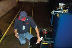
Figure 2. Check oil flow by porting the case drain line into a container of a known size and timing the flow rate.
Relief Valves
Many pressure-compensating pumps utilize a relief valve as a safety backup in case the compensator spool sticks in the closed position. The relief valve should be set 250 PSI above the pressure compensator’s setting. If the relief valve’s setting is above the compensator’s setting, no oil should flow through the relief valve spool. Therefore, the valve’s tank line should be at ambient temperature. If the compensator were to stick in the position shown in Figure 3, the pump would deliver maximum volume at all times. The excess oil not used by the system would return to the tank through the relief valve. A significant amount of heat would be generated if this occurred.
Often the pressure in the system is randomly adjusted in an attempt to make the machine run better. If the local knob-turner sets the compensator pressure above the relief valve setting, excess oil will return to the tank through the relief, causing the oil temperature to rise 30 or 40 degrees. If the compensator fails to shift or is set above the relief valve setting, a tremendous amount of heat will be generated.
Assuming the maximum pump volume is 30 GPM and the relief valve is set to 1,450 PSI, the heat generation can be determined. If a 30-horsepower electric motor is used to drive this system (HP = 30 x 1,450 x 0.000583 or 25), then 25 horsepower will be converted to heat when in the idle mode. Since 746 watts equals 1 horsepower, 18,650 watts (746 x 25) or 18.65 kilowatts of electrical energy will be wasted.
Other valves used in the system such as accumulator dump valves and air bleed valves could also fail open and permit oil to bypass to the reservoir at high pressure. The tank lines of these valves should beat ambient temperature. Bypassing of the cylinder piston seals is another common cause of heat.
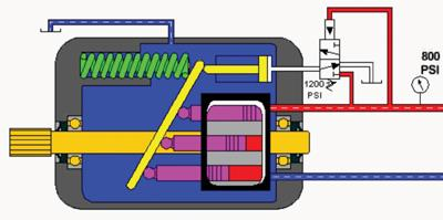
Figure 3. This illustration shows a variable-displacement, pressure-compensating pump in normal
operation.
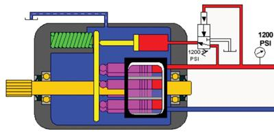
Figure 4. As pressure increases to 1,200 PSI, note the changes in the pump’s compensator spool,
internal cylinder and swashplate.
Heat Removal
The heat exchanger or cooler should be maintained to ensure excess heat is removed. If an air-type heat exchanger is used, the cooler fins should be cleaned on a regularly scheduled basis. A degreaser may be necessary to clean the fins. The temperature switch that turns on the cooler fan should be set at 115 degrees F. If a water cooler is used, a water-modulating valve should be installed in the water line to regulate flow through the cooler tubes to 25 percent of the oil flow.
The reservoir should be cleaned at least once per year. Otherwise, sludge and other contaminants not only can coat the bottom of the reservoir but also the sides as well. This would allow the reservoir to act as an incubator instead of dissipating the heat to the atmosphere.
I recently was at a plant where the oil temperature on a stacker was 350 degrees. It was discovered that the pressures were out of adjustment, the manual accumulator dump valve was partially open and oil was continually ported through a flow control that drove a hydraulic motor. The motor drove outfeed chains that only operated five to 10 times during an eight-hour shift. The pump compensator and relief valve were properly set, the manual valve was closed and the electrician de-energized the motor’s directional valve, blocking flow through the flow control. When the unit was checked 24 hours later, the oil temperature had dropped to 132 degrees F. Of course, the oil had broken down, and the system had to be flushed to remove sludge and varnish. New oil also had to be added to the unit.
All of these issues were man-induced. The local knob-turner had set the compensator above the relief valve, enabling the pump volume to return to the tank at high pressure when nothing on the stacker was operating. Someone had also failed to fully close the manual valve, thereby permitting oil to bypass back to the tank at high pressure. In addition, the system had been improperly programmed to allow the chains to run continuously when they should have only been driven if a load was to be removed from the stacker. The next time a heat problem occurs in one of your systems, look for oil that is flowing from a higher pressure to a lower pressure in the system. That’s where you’ll likely find your problem.
